- 您现在的位置:买卖IC网 > Sheet目录203 > APMR0016 (Red Lion Controls)MOD APMR 3-PH VAULT DET DIN RAIL
�� �
�
�FUNCTION DESCRIPTIONS�
�PHASE� UNBALANCE�
�Unbalance� occurs� in� 3� phase� systems� when� single� phase� loads� are� added�
�without� regard� to� voltage� effects� on� the� remaining� phases.� This� unbalance� in�
�phase� voltage� causes� excessive� motor� current� producing� temperatures� in� excess�
�of� specifications.� The� relationship� between� voltage� unbalance� and� percentage�
�of� temperature� rise� is� approximately� the� square� of� the� percent� voltage�
�unbalance� times� two.� ie.,� -� %� temperature� rise� =� (%� unbalance� 2� X� 2).�
�Therefore,� a� 4%� voltage� unbalance� will� result� in� approximately� a� 32%�
�increase� in� winding� temperature.� The� effect� of� temperature� rise� is� immediate�
�failure� of� winding� insulation� if� unbalance� is� severe� as� with� single� phasing.� If�
�unbalance� is� slight,� gradual� winding� degradation� will� result� in� premature�
�insulation� failure.� The� APMR� will� detect� slight� unbalances� that� thermal� and�
�magnetic� devices� usually� miss.�
�PHASE� LOSS�
�Phase� Loss� is� an� extreme� case� of� unbalance� known� as� “single� phasing”�
�where� a� total� loss� of� one� of� the� phases� occurs.� During� this� condition� the� motor�
�will� continue� to� run� and� the� full� current� is� drawn� from� the� remaining� phases.�
�Unless� the� motor� is� lightly� loaded� motor� failure� will� occur.� The� APMR� will�
�detect� Phase� Loss� even� with� regenerated� voltages� present.�
�PHASE� REVERSAL�
�Reversing� any� two� of� the� three� phases� will� cause� a� motor� to� rotate� opposite�
�the� intended� direction� causing� damage� to� machinery.� Reversal� can� occur� during�
�maintenance� of� distribution� systems.� The� APMR� will� detect� Phase� Reversal�
�regardless� of� load� conditions.�
�UNDERVOLTAGE�
�Undervoltage� can� occur� during� Brownouts,� excessive� system� loading� and�
�motor� startups.� An� undervoltage� Time� Delay� is� provided� with� the� undervoltage�
�detection� to� eliminate� false� tripping� during� startups� when� a� motor� draws� many�
�times� its� operating� current.�
�EMC� INSTALLATION� GUIDELINES�
�Although� this� unit� is� designed� with� a� high� degree� of� immunity� to�
�ElectroMagnetic� Interference� (EMI),� proper� installation� and� wiring� methods�
�must� be� followed� to� ensure� compatibility� in� each� application.� The� type� of� the�
�electrical� noise,� source� or� coupling� method� into� the� unit� may� be� different� for�
�various� installations.� Cable� length,� routing� and� shield� termination� are� very�
�important� and� can� mean� the� difference� between� a� successful� or� a� troublesome�
�installation.� Listed� below� are� some� EMC� guidelines� for� successful� installation�
�in� an� industrial� environment.�
�1.� The� unit� should� be� mounted� in� a� metal� enclosure,� that� is� properly� connected�
�to� protective� earth.�
�a.� If� the� bezel� is� exposed� to� high� Electro-Static� Discharge� (ESD)� levels,�
�above� 4� Kv,� it� should� be� connected� to� protective� earth.� This� can� be� done�
�by� making� sure� the� metal� bezel� makes� proper� contact� to� the� panel� cut-out�
�or� connecting� the� bezel� screw� with� a� spade� terminal� and� wire� to�
�protective� earth.�
�2.� Use� shielded� (screened)� cables� for� all� Signal� and� Control� inputs.� The� shield�
�(screen)� pigtail� connection� should� be� made� as� short� as� possible.� The�
�connection� point� for� the� shield� depends� somewhat� upon� the� application.�
�Listed� below� are� the� recommended� methods� of� connecting� the� shield,� in�
�order� of� their� effectiveness.�
�a.� Connect� the� shield� only� at� the� panel� where� the� unit� is� mounted� to� earth�
�ground� (protective� earth).�
�b.� Connect� the� shield� to� earth� ground� at� both� ends� of� the� cable,� usually� when�
�the� noise� source� frequency� is� above� 1� MHz.�
�c.� Connect� the� shield� to� common� of� the� unit� and� leave� the� other� end� of� the�
�shield� unconnected� and� insulated� from� earth� ground.�
�3.� Never� run� Signal� or� Control� cables� in� the� same� conduit� or� raceway� with� AC�
�power� lines,� conductors� feeding� motors,� solenoids,� SCR� controls,� and�
�heaters,� etc.� The� cables� should� be� run� in� metal� conduit� that� is� properly�
�grounded.� This� is� especially� useful� in� applications� where� cable� runs� are� long�
�and� portable� two-way� radios� are� used� in� close� proximity� or� if� the� installation�
�is� near� a� commercial� radio� transmitter.�
�4.� Signal� or� Control� cables� within� an� enclosure� should� be� routed� as� far� away� as�
�possible� from� contactors,� control� relays,� transformers,� and� other� noisy�
�components.�
�2�
�5.� In� extremely� high� EMI� environments,� the� use� of� external� EMI� suppression�
�devices,� such� as� ferrite� suppression� cores,� is� effective.� Install� them� on� Signal�
�and� Control� cables� as� close� to� the� unit� as� possible.� Loop� the� cable� through� the�
�core� several� times� or� use� multiple� cores� on� each� cable� for� additional� protection.�
�Install� line� filters� on� the� power� input� cable� to� the� unit� to� suppress� power� line�
�interference.� Install� them� near� the� power� entry� point� of� the� enclosure.� The�
�following� EMI� suppression� devices� (or� equivalent)� are� recommended:�
�Ferrite� Suppression� Cores� for� signal� and� control� cables:�
�Fair-Rite� #� 0443167251� (RLC� #FCOR0000)�
�TDK� #� ZCAT3035-1330A�
�Steward� #28B2029-0A0�
�Line� Filters� for� input� power� cables:�
�Schaffner� #� FN610-1/07� (RLC� #LFIL0000)�
�Schaffner� #� FN670-1.8/07�
�Corcom� #1VB3�
�Corcom� #1VR3�
�Note:� Reference� manufacturer� ’s� instructions� when� installing� a� line� filter.�
�6.� Long� cable� runs� are� more� susceptible� to� EMI� pickup� than� short� cable� runs.�
�Therefore,� keep� cable� runs� as� short� as� possible.�
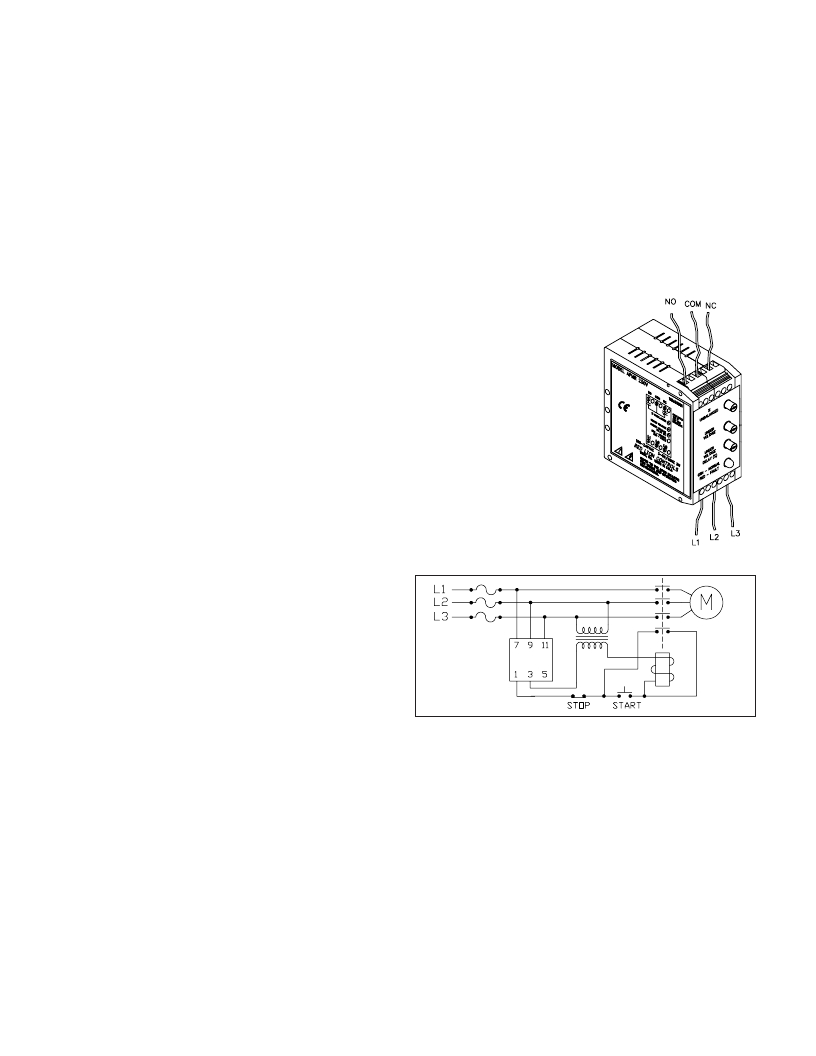
�WIRING� CONNECTIONS�
�All� conductors� should� meet� voltage�
�and� current� ratings� for� each� terminal.�
�Also,� cabling� should� conform� to�
�appropriate� standards� of� good�
�installation,� local� codes� and� regulations.�
�It� is� recommended� that� power� supplied� to�
�the� unit� be� protected� by� a� fuse� or� circuit�
�breaker.� When� wiring� the� unit,� use� the�
�number� on� the� label� to� identify� the�
�position� number� with� the� proper�
�function.� Strip� wire,� leaving�
�approximately� 1/4"� (6mm)� of� bare� wire�
�exposed.� Insert� the� wire� into� the� terminal,�
�and� tighten� the� screw� until� the� wire� is�
�clamped� tightly.�
�发布紧急采购,3分钟左右您将得到回复。
相关PDF资料
APS INT2012
INVERTER 2000W 230VAC OUT
APS1012
INVERTR 1000W 12VDC 2OUT W/CHRGR
APS1250
INVERTER W/BATT CHARGE 1250W
APS1524
INVERTER 1500W HARDWIRE OUTPUT
APS2424
INVERTR 2400W 24VDC W/CHRGR
APS2448UL
INVERTER 2400W 48VDC OR 120VAC
APS3636VR
INVERTER 3600W 36VDC OR 120VAC
APS512
INVERTER 500W 12VDC 2OUT W/CHRGR
相关代理商/技术参数
APMR0086
制造商:Red Lion Controls 功能描述:SIGNAL CONDIT MOD, 3 PH FAULT DET 380V 制造商:Red Lion Controls 功能描述:3 PHASE FAULT DETECTOR 380VAC
APMR0096
制造商:Red Lion Controls 功能描述:Relay, Analog Phase Mod, 480 制造商:Red Lion Controls 功能描述:3 PHASE FAULT DETECTOR 480VAC
APMS-10GRCF
制造商:Honeywell / Clarostat 功能描述:Wash Process Sensor 3-Pin 制造商:Honeywell Sensing and Control 功能描述:Magnetic Sensors 制造商:Honeywell Sensing and Control 功能描述:Wash Process Sensor 3-Pin
APMS-10GRCF-18
制造商:Honeywell / Clarostat 功能描述:Wash Process Sensor 3-Pin 制造商:Honeywell Sensing and Control 功能描述:Magnetic Sensors 制造商:Honeywell Sensing and Control 功能描述:Wash Process Sensor 3-Pin
APMS-10GRCF-50
制造商:Honeywell / Clarostat 功能描述:Wash Process Sensor 3-Pin 制造商:Honeywell Sensing and Control 功能描述:Magnetic Sensors 制造商:Honeywell Sensing and Control 功能描述:Wash Process Sensor 3-Pin
APMS-10GRCF-KIT
制造商:Honeywell Sensing and Control 功能描述:Wash Process Sensor 3-Pin
AP-MSD01GISI-T
功能描述:Memory Card microSD? 1GB SLC 制造商:apacer memory america 系列:- 零件状态:有效 存储器类型:microSD? 存储容量:1GB 速度:- 技术:SLC 工作温度:-40°C ~ 85°C 标准包装:1
AP-MSD02GIDI-T
功能描述:Memory Card microSD? 2GB SLC 制造商:apacer memory america 系列:- 零件状态:有效 存储器类型:microSD? 存储容量:2GB 速度:- 技术:SLC 工作温度:-40°C ~ 85°C 标准包装:1